|
|
©1999-2003. All rights reserved. |
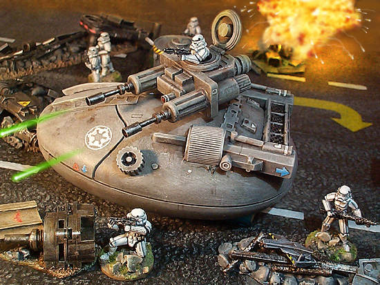
Hovertank
Materials
| |||
 |
Stage 2 - Turret

Basic Shape
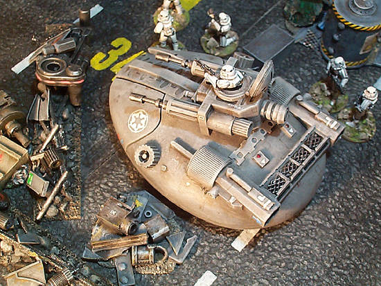
The turret is basically the D-type connector from the end of the mouse
lead. (It was an old fashioned serial port mouse). The D connector itself
was covered with a small rectangle of card, and a piece of sprue was
stuck on as an optical sight. To further disguise the shape I stuck
a couple of boxes removed from the mouse circuit board on the top of
the connector socket.
Swivel Mounting
Underneath the turret, the plastic was cut away and a small bolt was
glued on with its head in the cavity. The bolt fits through a hold made
in the top of the tank and a nut secures it in place.
Cannon
The cannon are formed from the mouse connector screws, unscrewed
from their sockets and then glued on in front. The screw threads at
the tips were covered up by gluing on a short length of metal tube.
The ribbed cylinders at the back of the cannon are from a Zoid.
Hatch & trooper
The hatch is a plastic washer, and the lid is a wheel from a Zoid. The
stormtrooper was cut in half with clippers and glued on. His right arm
was also cut off below the shoulder pad and rebuilt in putty.
Stage 3 - Surface Detail

![]() These
pieces are rubbery connectors from a large Zoid. The central blob has
been picked out in silver.
These
pieces are rubbery connectors from a large Zoid. The central blob has
been picked out in silver.
The flat rectangles on the front of the tank, with the slots and curved holes in them, are razorblades. They were stuck down with the superglue, and a thick piece of card was stuck down over the sharp edges. The air intake on the right hand side is from a WWII plane kit.
On the back of the tank the rectangle with notched edges and circular holes in it is a plastic packer from the razor head.
 |
Stage 4 - Engines

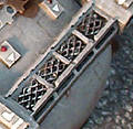 The
ventilation grilles at the rear are made from an upside down razor
head. Car body repair mesh was
superglued into the holes, and the head was stuck to the main body
with polystyrene cement.
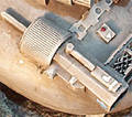 The
main body of the engine was made from the end of a disposable razor
handle. This was then decorated with a couple of bits of sprue and
a rectangle of card. Another piece of sprue was stuck on the tank
body in front of the engine. The grooved cylinder is a section from
a large felt tip pen lid. Care should be taken to stick the two engines
on symmetrically.
Stage 5 - Painting

The tank was painted using more or less the same process as this
tie fighter, except that the colour used was a plain grey and not
a blue grey. Small lines and rectangles were painted on at the end
in dark brown ink to make the surface more interesting.
 The
Imperial symbol on the front was downloaded from a website and printed
out, before being cut out with a sharp scalpel. This was then stencilled
onto the tank and then a fine brush was used to neaten it up (particularly
the ring round the edge).


